
Lining design
Share equipment drawings, shell dimensions, penetrations, lining thickness and orientation so module layout and quantity can be reviewed.
Engineered furnace-lining systems
Pre-compressed 1260°C and 1425°C ceramic fiber modules for efficient furnace and kiln lining installation.
Product overview
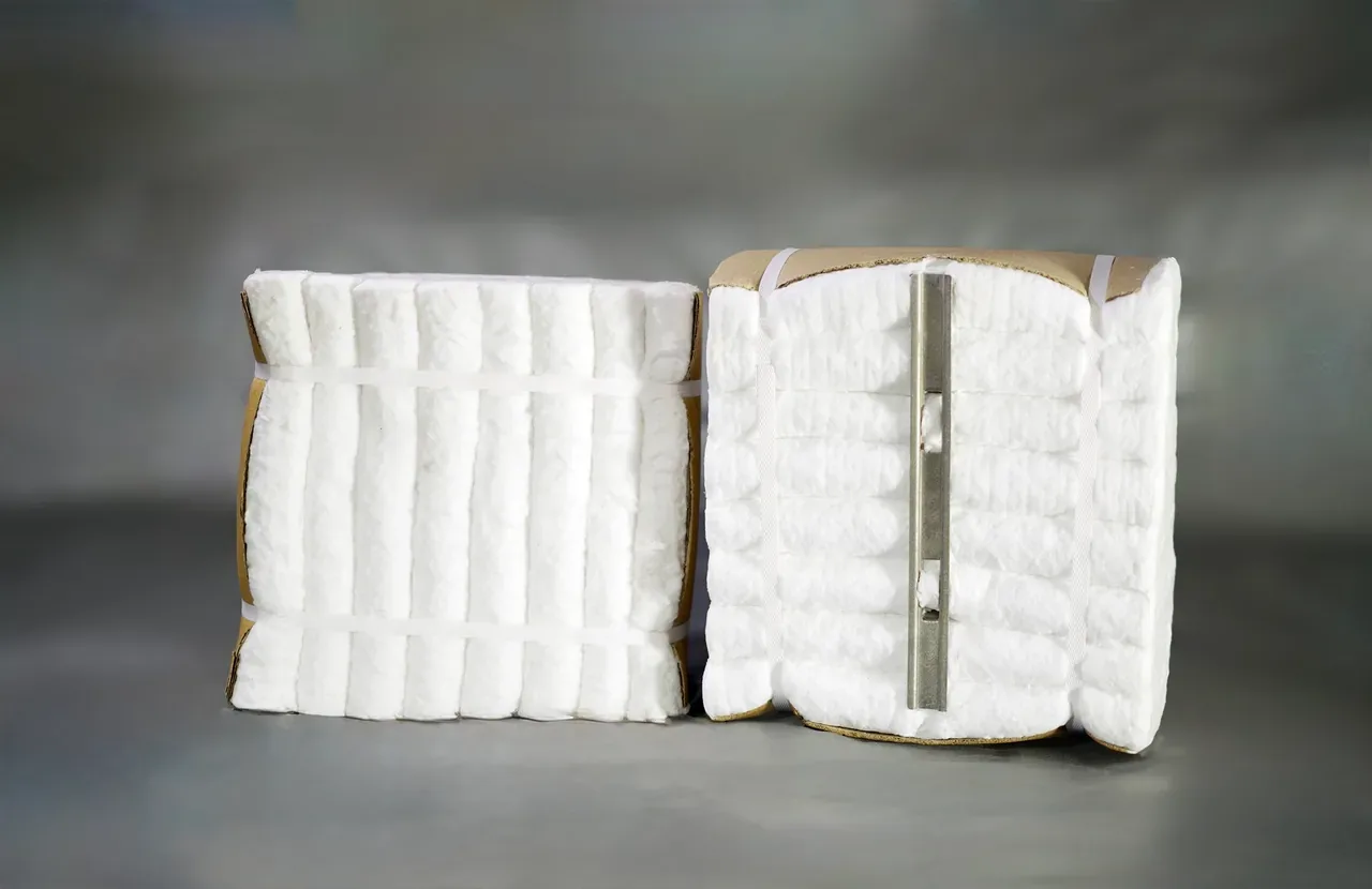
Ceramic fiber modules are made from folded and compressed needled blanket with a purpose-selected anchoring system. They are designed to simplify installation and provide a stable, energy-efficient lining for industrial furnaces, kilns and other heat-processing equipment.
Refractory ceramic fiber (RCF) identifies the alumina-silicate fiber family used in these products. Confirm the selected grade’s composition, service limits and safety data for your application.
Available specifications are confirmed for each enquiry according to application, quantity and required delivery schedule.
Request a quotationProduct details
Ceramic fiber modules combine folded, pre-compressed blanket with an integrated anchoring arrangement to create an efficient lining unit for furnaces, kilns, heaters and high-temperature process equipment. Pre-compression helps accommodate fiber shrinkage and maintain pressure between adjacent modules when the lining is installed correctly.
Ranipa supplies ceramic fiber modules for export from India in 1260°C classification and 1425°C zirconia grades. A 305 × 305 mm face size is available with 128, 160, 180 and 192 kg/m³ densities, multiple lining thicknesses and Cerlock or Anchor-Loc3 configurations. Module production normally begins after the design and commercial order are finalized, so quantity and lead-time planning are important.
A module is part of an engineered lining system rather than a stand-alone commodity. Anchor alloy, stud or bolting arrangement, module orientation, compression, joint treatment and installation pattern must suit the equipment shell, operating temperature, atmosphere and mechanical conditions. Drawings are strongly recommended for project enquiries.
Ranipa coordinates module identification, technical documents, export packing and shipment requirements with established manufacturing capability. For a useful quotation, buyers should share furnace drawings, module size and density, lining thickness, anchor preference, quantity, operating conditions and destination port.
Characteristics
Industry use
Technical information
Values shown are an overview of the currently available range. Final specification and tolerances are confirmed in the commercial documentation.
| Classification temperatures | 1260°C and 1425°C |
|---|---|
| Available densities | 128, 160, 180 and 192 kg/m³ |
| Standard face dimensions | 305 × 305 mm |
| Standard thickness range | 100–300 mm, subject to configuration |
| Construction | Folded, pre-compressed ceramic fiber blanket |
| Anchoring options | Cerlock sliding type and Anchor-Loc3 bolting type |
| Colour | White |
| Thermal-conductivity test method | ASTM C177 |
Selection note: Module design, anchor alloy and installation pattern must be selected for the equipment geometry, operating temperature, atmosphere and mechanical conditions.
Selection guidance
A complete enquiry helps align the product configuration with the service environment and export requirement.
Share equipment drawings, shell dimensions, penetrations, lining thickness and orientation so module layout and quantity can be reviewed.
Anchor type and alloy must match the attachment method, operating temperature, atmosphere and corrosion conditions.
Density and installed compression affect handling and lining integrity. These values should be specified consistently across the project.
Module performance depends on correct welding or bolting, layout, joint treatment and installation quality. Qualified installation supervision is recommended.
Buyer questions
The range includes Cerlock sliding-type and Anchor-Loc3 bolting-type configurations in 1260°C and 1425°C classifications, subject to density, thickness and project design.
A common standard face dimension is 305 × 305 mm. Thickness typically ranges from 100 to 300 mm, subject to configuration and manufacturing confirmation.
Provide drawings, classification or operating temperature, face size, lining thickness, density, anchor system or alloy, total quantity, equipment application and destination.
A preliminary discussion is possible, but a reliable project quotation and layout normally require equipment dimensions or drawings and confirmation of the operating conditions.
Related insulation
Compare the other product forms in Ranipa’s current ceramic fiber insulation export range.
Ceramic fiber insulation
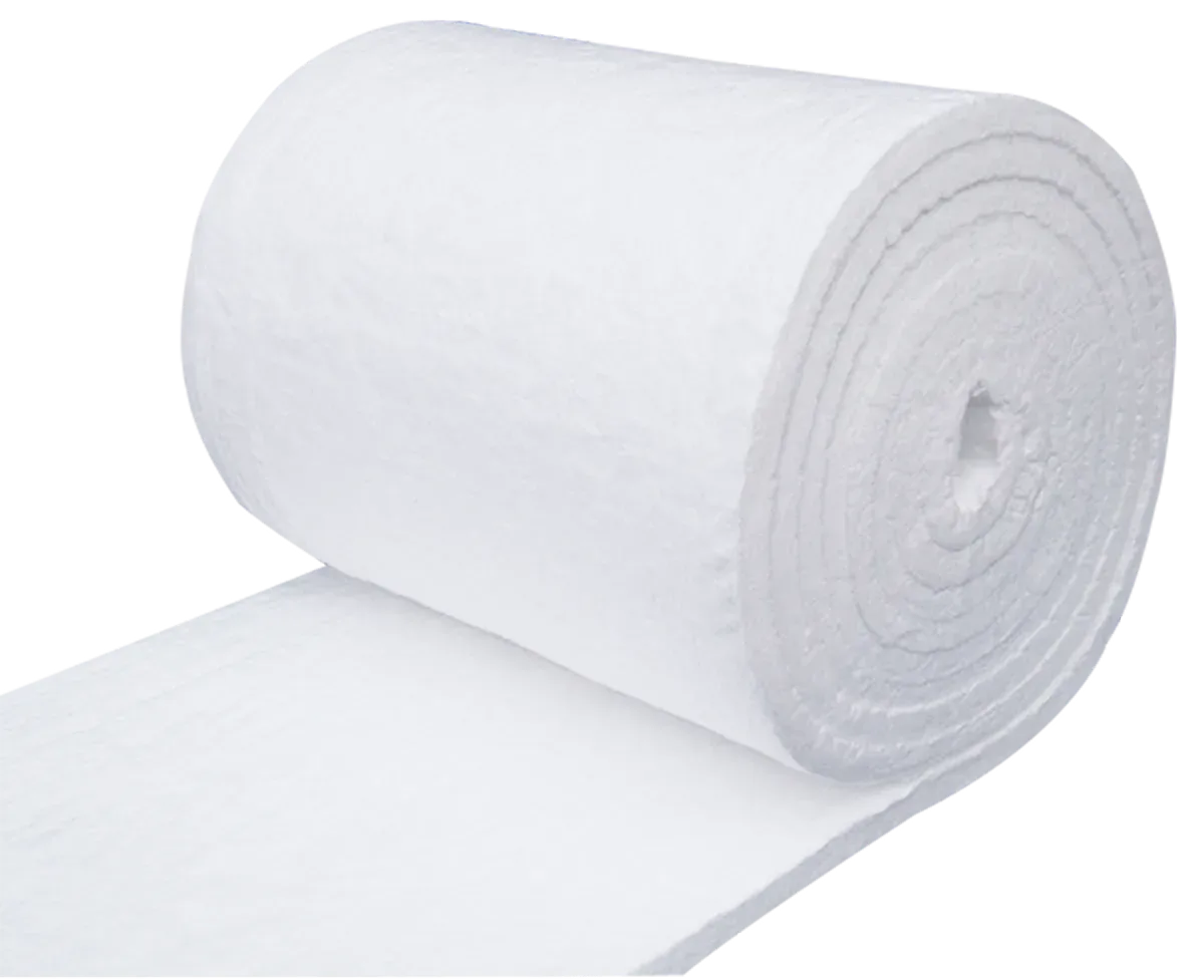
Needled, flexible ceramic fiber insulation in 1260°C and 1425°C grades for industrial thermal systems.
View ceramic fiber blanket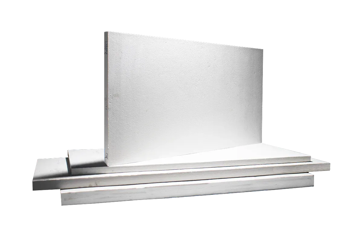
Ceramic fiber insulation
Rigid, machinable ceramic fiber board in 1100°C, 1260°C and 1425°C grades for industrial insulation.
View ceramic fiber boardProduct enquiry
Include the grade, density, thickness or dimensions, quantity, application and destination port for a more precise response.